- **The Carbide Inserts Identification Guide** provides a comprehensive overview of carbide inserts, their grades, dimensions, shapes, geometries, coatings, substrates, and application-specific designs. It covers essential topics like cutting parameters, chipbreaker control, wear resistance, and optimizing insert selection for different machining tasks. This comprehensive resource empowers machinists with the knowledge to decode carbide inserts and make informed decisions that enhance machining efficiency and productivity.
Decoding Carbide Inserts: A Comprehensive Guide
Carbide inserts, a crucial component in the machining world, are meticulously engineered cutting tools that elevate performance and precision in various manufacturing industries. These inserts are designed with an array of attributes that influence their cutting capabilities, durability, and efficiency. Understanding the intricacies of carbide inserts empowers machinists to make informed decisions, optimizing cutting processes and maximizing productivity.
Insert Grade: The Foundation of Performance
The insert grade, a unique combination of materials and properties, forms the foundation of an insert’s performance. Each grade is tailored to specific cutting tasks, dictated by the composition of the cutting tool and workpiece materials. By comprehending the relationship between insert grade and its machining capabilities, machinists can select the ideal insert for their specific application.
Insert Grade: The Building Blocks of Performance
In the realm of machining, carbide inserts stand as the unsung heroes, transforming raw materials into precise components with unmatched efficiency. At the heart of these inserts lies a crucial element: insert grade. This seemingly simple concept holds the key to unlocking the full potential of carbide inserts, dictating their performance across a wide range of machining applications.
Understanding Insert Grade
Insert grades are essentially recipes that determine the composition of the carbide from which inserts are manufactured. This composition influences an array of critical properties, including:
- Hardness: Resists plastic deformation, enabling inserts to withstand high cutting forces.
- Toughness: Imparts resistance to fracture, ensuring insert integrity under shock loads.
- Wear Resistance: Prevents abrasive wear and extends insert life, reducing downtime and maintenance costs.
The Correlation Between Grade and Machining Capabilities
The specific grade of an insert is tailored to the intended machining application. For instance, inserts designed for roughing operations (removing large amounts of material quickly) prioritize hardness. Conversely, inserts employed in finishing operations (creating fine surface finishes) emphasize toughness.
Grade Composition and Designation
Insert grades are typically denoted by a series of characters and numbers. The first letter indicates the primary carbide compound, such as K for tungsten carbide or H for tantalum carbide. Subsequent letters may represent additional alloying elements, such as Ti for titanium or Cr for chromium. Numbers indicate the relative proportions of these elements.
For example, the grade K20 signifies a tungsten carbide insert with 20% titanium. This insert would exhibit high hardness and wear resistance, making it suitable for roughing operations.
Choosing the Right Insert Grade
Selecting the appropriate insert grade is paramount for optimizing machining performance. Factors to consider include:
- Workpiece Material: The hardness and toughness of the workpiece determine the required insert grade.
- Cutting Operation: The specific machining operation (roughing, finishing, etc.) dictates the ideal grade properties.
- Machine Specifications: The power and rigidity of the machine can influence the suitable insert grade.
Understanding insert grade is the gateway to unlocking the full potential of carbide inserts. By carefully selecting the right grade for the job, machinists can achieve exceptional performance, reduce downtime, and maximize productivity.
ISO Code: Unraveling the Key to Insert Dimensions and Shapes
In the intricate world of machining, carbide inserts reign supreme as powerful tools capable of carving intricate designs with precision and efficiency. To decipher the language of these cutting-edge tools, one must delve into the intricacies of ISO codes, a standardized system that unlocks the secrets of insert sizes and geometries.
The Standardization of ISO Codes
The International Organization for Standardization (ISO) has meticulously established a comprehensive system of codes that classifies carbide inserts based on their dimensions and shapes. This standardization ensures a universal language for engineers and manufacturers, allowing them to communicate seamlessly about insert specifications.
Unlocking Insert Sizes
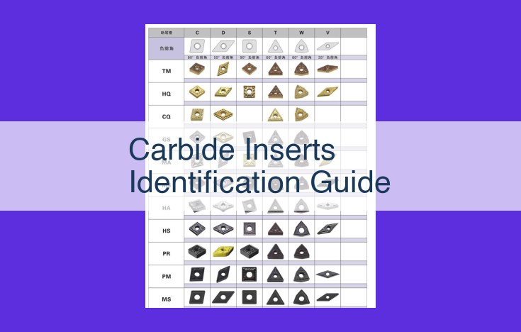
ISO codes ingeniously convey the critical dimensions of carbide inserts. The first portion of the code, typically comprising two digits, denotes the insert shape, such as square, triangular, or circular. This provides a quick visual reference to the insert’s form.
The subsequent characters in the code represent the insert size. These numbers indicate the length, width, and thickness of the insert, ensuring that it fits precisely into the designated toolholder. By specifying these dimensions, ISO codes eliminate guesswork and ensure a secure and efficient connection between insert and holder.
Unraveling Insert Geometries
Beyond dimensions, ISO codes also provide insights into the insert geometry. This refers to the angles and contours that define the cutting action of the insert. The code indicates the rake angle, which influences chip formation and tool life, as well as the clearance angle, which prevents rubbing against the workpiece and premature wear.
Moreover, ISO codes specify the edge preparation of the insert. This includes the geometry of the cutting edge, such as positive, negative, or neutral. Each edge preparation imparts unique characteristics to the insert, affecting its chip formation, cutting forces, and overall performance.
Benefits of ISO Codes
The standardization of ISO codes offers numerous advantages:
- Clarity and Precision: Engineers can communicate insert specifications clearly and accurately, minimizing errors and misunderstandings.
- Universal Understanding: The global recognition of ISO codes facilitates seamless collaboration among manufacturers and suppliers from different regions.
- Efficient Tool Selection: By deciphering ISO codes, engineers can quickly identify inserts tailored to specific machining tasks and workpiece materials.
- Optimized Performance: The precise information provided by ISO codes enables engineers to fine-tune cutting parameters, such as speed and feed rates, for maximum insert performance.
Geometry 101: Angles and Edges that Matter
In the realm of machining, carbide inserts reign supreme, their performance intricately intertwined with their angles and edges. These geometrical nuances profoundly influence cutting efficiency and workpiece quality. Let’s delve into the key insert angles and unravel their impact on machining prowess.
Rake Angle:
The rake angle refers to the angle between the rake face of the insert and the cutting direction. This angle determines how easily the insert penetrates the workpiece material. A positive rake angle (insert face tilted away from the cutting direction) promotes smoother cutting, while a negative rake angle (insert face tilted towards the cutting direction) provides increased strength for heavy-duty operations.
Clearance Angle:
The clearance angle is the angle between the clearance face of the insert and the workpiece surface. It ensures that the insert does not rub against the workpiece, reducing friction and heat generation. A larger clearance angle allows for deeper cuts, but it can also weaken the insert’s cutting edge.
Relief Angle:
The relief angle is the angle between the relief face of the insert and the insert’s cutting edge. It prevents the insert from rubbing against the machined surface, improving surface finish and tool life. A smaller relief angle provides higher cutting forces, while a larger relief angle reduces cutting forces and improves surface quality.
Variations in Insert Angles:
Different insert geometries are designed for specific cutting applications. Roughing inserts with a large positive rake angle and small clearance angle excel at removing large amounts of material quickly. Finishing inserts with a small positive rake angle and large clearance angle create smooth, precise surfaces. Interrupted cutting inserts with a negative rake angle and large clearance angle withstand high impact loads during interrupted cuts.
Understanding and optimizing insert angles is paramount for maximizing cutting performance. By selecting the right angles for the job, you can ensure efficient and precise machining operations, delivering superior workpiece quality and enhanced productivity.
Cutting Edge Shape: Shaping the Cutting Action
- Explain the different cutting edge shapes (positive, negative, neutral) and how they influence chip formation and cutting forces.
Cutting Edge Shape: Shaping the Cutting Action
In the world of machining, cutting edge shape plays a crucial role in determining the efficiency and effectiveness of cutting operations. Just like a painter’s brushstroke, the shape of the cutting edge influences the way chips are formed and the forces exerted during cutting.
There are three primary cutting edge shapes:
Positive Cutting Edge:
- With a positive rake angle, a positive cutting edge slices through the workpiece material, creating continuous and thin chips.
- This shape is ideal for materials that produce long, stringy chips, such as aluminum and copper.
- It results in lower cutting forces and improved surface finish.
Negative Cutting Edge:
- Featuring a negative rake angle, a negative cutting edge pushes through the workpiece material, producing thick and broken chips.
- This shape is suitable for materials that tend to form gummy chips, such as steel and stainless steel.
- It provides higher cutting forces but offers greater stability in challenging cutting conditions.
Neutral Cutting Edge:
- Lying somewhere between positive and negative, a neutral cutting edge balances chip formation and cutting forces.
- It is a versatile option suitable for a wide range of materials and applications.
- It offers a compromise between the benefits of positive and negative cutting edges.
Understanding the impact of cutting edge shape on chip formation and cutting forces is crucial for selecting the right insert for the job. By matching the cutting edge shape to the workpiece material and cutting conditions, you can optimize machining performance, improve productivity, and extend insert life.
Coating for Enhanced Performance: Unlocking the Potential of Carbide Inserts
In the realm of machining, carbide inserts reign supreme as indispensable tools. To further enhance their capabilities, various coatings are meticulously applied to their surfaces, unlocking a world of benefits that elevate their performance and durability.
Titanium Nitride (TiN): The Versatile Shield
TiN coating is a ubiquitous choice for carbide inserts, offering a versatile and cost-effective solution. Its thin, golden layer not only improves hardness but also reduces friction and wear. TiN coatings are ideal for general-purpose machining, providing a balance of durability and affordability.
Titanium Aluminum Nitride (TiAlN): A Tough Contender
TiAlN coatings take a step further, delivering exceptional hardness and toughness. This resilient surface withstands abrasive conditions remarkably well, making it the preferred choice for machining hardened steels and abrasive materials. TiAlN coatings extend insert life, allowing for longer periods between replacements.
Chemical Vapor Deposition (CVD) Coatings: Precision and Performance
CVD coatings are applied through a chemical process, resulting in precise and uniform layers. They offer superior hardness, wear resistance, and thermal stability. CVD coatings are specifically designed for high-speed machining operations, where extreme temperatures and demanding cutting parameters are present.
Enhanced Durability and Wear Resistance
Coatings significantly increase the durability of carbide inserts, enabling them to withstand the rigors of machining operations without sacrificing cutting efficiency. By reducing friction and wear, coatings prolong insert life, minimizing downtime for replacements and maximizing productivity.
Specific Applications: Tailored to the Task
Different coatings are tailored to specific machining applications. For roughing operations, where high material removal rates are prioritized, coatings that prioritize toughness are preferred. For finishing operations, where precision and surface finish are paramount, coatings that emphasize hardness and sharpness are often employed.
By understanding the benefits and applications of various coatings, machinists can optimize their insert selection, maximizing the performance and efficiency of their cutting operations.
Substrate Matters: The Foundation of Carbide Inserts
Carbide inserts are the workhorses of machining, but their performance relies heavily on their underlying substrate. This substrate forms the backbone of the insert, giving it the strength, durability, and cutting capabilities needed to tackle various machining tasks.
Cemented Carbide: The Workhorse Material
Cemented carbide is the most widely used substrate for carbide inserts. It’s a combination of tungsten carbide and a binder metal, usually cobalt or nickel. Cemented carbide is extremely hard and wear-resistant, making it suitable for a wide range of cutting applications, from roughing to finishing.
-
Pros:
- High hardness and wear resistance
- Good strength and toughness
- Versatile and suitable for various cutting tasks
-
Cons:
- Susceptible to thermal cracking
- Can be brittle in certain applications
Ceramic: The High-Speed Option
Ceramic substrates offer exceptional cutting speeds and excellent wear resistance. They are typically made from aluminum oxide, silicon nitride, or cubic boron nitride. Ceramic inserts excel in high-speed machining and cutting hard materials like hardened steel and titanium.
-
Pros:
- Very high cutting speeds
- Exceptional wear resistance
- Chemically inert and corrosion-resistant
-
Cons:
- Lower toughness compared to cemented carbide
- More sensitive to thermal shock
Choosing the Right Substrate
Selecting the right substrate for your carbide inserts depends on the specific cutting application. For roughing and general machining, cemented carbide is a reliable choice. For high-speed machining and cutting hard materials, ceramic inserts offer superior performance.
Properties that Affect Insert Performance
- Hardness: The hardness of the substrate determines its resistance to abrasion and wear.
- Toughness: The toughness of the substrate measures its ability to resist chipping or breaking under impact loads.
- Fracture toughness: This measures the substrate’s resistance to crack propagation.
- Thermal conductivity: The thermal conductivity of the substrate affects its ability to dissipate heat.
Application-Specific Inserts: Tailoring to the Task
When choosing the right carbide insert for your machining task, it’s crucial to consider the specific requirements of the job. Inserts are meticulously designed to excel in various cutting applications, from demanding roughing operations to intricate finishing tasks and challenging interrupted cutting scenarios.
For roughing cuts, inserts with robust geometry and sharp cutting edges are essential. They possess ample chip space and a strong substrate to withstand the heavy forces and large chip loads encountered during this aggressive material removal process.
In contrast, finishing cuts necessitate inserts with precise geometry and polished cutting edges. These attributes ensure a smooth and accurate surface finish, minimizing the need for additional post-processing steps.
Interrupted cutting operations, characterized by frequent starts and stops, demand inserts with high wear resistance and toughness. Chip control becomes paramount to prevent chip jamming, and inserts with effective chipbreakers excel in these challenging conditions.
By selecting inserts tailored to the specific cutting task, you can maximize productivity, reduce downtime, and achieve superior results. It’s like having a specialized tool for every job, ensuring efficiency and precision in your machining operations.
Optimizing Cutting Parameters: Maximizing Machining Efficiency
When it comes to machining, choosing the right carbide insert is crucial. But to fully unlock its potential, you must also optimize the cutting parameters: speed, feed, and depth of cut. These parameters have a profound impact on your machining results, influencing everything from productivity to tool life.
Cutting Speed: The Racecar on the Track
Imagine a racecar speeding down the track. Cutting speed is like the racecar’s velocity; higher cutting speeds result in shorter machining times but can also increase tool wear. Conversely, lower cutting speeds extend tool life at the expense of efficiency.
Feed Rate: The Cogs in the Machine
Think of the feed rate as the cogs in a machine. It controls the rate at which the insert moves against the workpiece. A higher feed rate increases material removal, but again, at the potential cost of reduced tool life. Conversely, a lower feed rate minimizes wear but can result in slower machining.
Depth of Cut: Digging into the Material
The depth of cut is analogous to how deeply a digger plunges into the ground. A larger depth of cut removes more material per pass but can put significant stress on the insert. Conversely, a smaller depth of cut reduces stress but may require multiple passes to achieve the desired result.
Matching Parameters to Insert and Workpiece
The optimal cutting parameters vary depending on the insert grade and the properties of the workpiece being machined. For example, harder inserts can withstand higher cutting speeds and feed rates. Similarly, harder workpieces require lower cutting speeds and higher feed rates.
Experimentation and Refinement
Determining the ideal cutting parameters is an iterative process that involves experimentation and refinement. Start with recommended values and gradually adjust them based on observations of tool wear, workpiece quality, and cycle time.
Optimizing cutting speed, feed rate, and depth of cut is the key to maximizing machining efficiency and productivity. By carefully considering the insert grade, workpiece material, and desired results, you can fine-tune these parameters to achieve the perfect balance of performance and longevity.
Chipbreaker Control: Taming the Chips
- Discuss the role of chipbreakers in controlling chip formation, preventing clogging, and ensuring efficient cutting operations.
Chipbreaker Control: Taming the Unruly Chips
In the world of machining, chip formation plays a crucial role in determining the efficiency and quality of the cutting process. Uncontrolled chips can wreak havoc, causing clogging, hindering tool performance, and compromising workpiece surface finish. Enter chipbreakers, the unsung heroes that tame these unruly byproducts.
Chipbreakers are strategically designed features on cutting inserts that disrupt the chip formation process. They create a controlled point of failure, guiding the chips into smaller, manageable fragments. This prevents them from forming long, continuous strands that can wrap around the cutting tool or clog the machining area.
By effectively breaking the chips, chipbreakers ensure smooth and uninterrupted cutting operations. They reduce friction between the chips and the insert, minimizing tool wear and improving surface finish. Additionally, they prevent chip clogging, which can lead to tool breakage, machine downtime, and costly delays.
Consider this analogy: Imagine a carpenter working with a hand saw. Without a chipbreaker, the sawdust would form long, tangled strands that hinder the sawing process. However, a saw blade with a chipbreaker would effectively break down the sawdust into manageable fragments, allowing the carpenter to cut with greater precision and efficiency.
In the same vein, chipbreakers optimize the machining process by controlling chip formation. They contribute to longer tool life, reduced machine downtime, and improved workpiece quality. As a result, they play a pivotal role in maintaining productivity and achieving optimal cutting outcomes.
Wear Resistance: Longevity in the Cutting World
When it comes to machining, the longevity of your cutting tools is paramount for efficient and productive operations. Among the key factors that determine a cutting tool’s lifespan is its wear resistance. Understanding wear resistance and its implications is crucial for maximizing insert life and overall productivity.
Importance of Wear Resistance
Wear resistance refers to the ability of a cutting tool to resist wear and tear under cutting conditions. Excessive wear can lead to:
- Reduced cutting efficiency and productivity
- Compromised part quality
- Increased downtime due to tool changes
- Higher production costs
Assessing Wear Resistance
Assessing wear resistance is typically done through wear tests. These tests evaluate the tool’s ability to retain its sharpness and cutting edge integrity over a specified period or number of cutting cycles. The results provide insights into the tool’s wear rate, which is expressed as the amount of wear per unit of cutting time or distance.
Factors Affecting Insert Life and Productivity
Several factors influence the wear resistance of carbide inserts and, consequently, their insert life and productivity:
-
Insert Grade: The composition and properties of the insert grade directly impact its wear resistance. Hardened grades, such as those with higher cobalt content, offer improved wear resistance.
-
Cutting Conditions: The cutting speed, feed rate, and depth of cut affect the amount of heat and friction generated during cutting. Excessive heat can accelerate wear, while appropriate cutting conditions can minimize it.
-
Workpiece Material: The hardness and abrasiveness of the workpiece material can significantly influence insert wear. Harder materials require tougher inserts with higher wear resistance.
-
Lubrication: Adequate lubrication reduces friction and heat, extending insert life.
-
Chip Control: Efficient chip removal prevents chip welding and clogging, which can accelerate wear.
Tips for Enhancing Wear Resistance
-
Proper Insert Selection: Choose inserts with the right grade and geometry for the cutting task and workpiece material.
-
Optimized Cutting Parameters: Determine the optimal cutting speed, feed rate, and depth of cut to minimize wear.
-
Lubrication and Chip Management: Use coolant or cutting fluids to lubricate the cutting zone and facilitate chip removal.
-
Regular Maintenance: Inspect inserts regularly for signs of wear and replace them promptly to prevent further damage.
By understanding and optimizing factors that affect wear resistance, manufacturers can significantly improve insert life and productivity, resulting in increased efficiency, reduced costs, and enhanced part quality.