Coil pack wiring harness testing is crucial for ensuring optimal engine performance. It involves conducting open/short circuit tests to detect electrical faults, continuity tests to verify circuit connectivity, insulation resistance tests to check electrical isolation, and hi-pot tests to assess insulation strength. Functional testing validates the harness’s actual performance, while environmental testing ensures its reliability under harsh conditions. Proper coil pack wiring harness testing helps prevent engine misfires, rough idle, and poor fuel efficiency.
Coil Pack Wiring Harness Testing: Unraveling the Secrets of Ignition
In the intricate tapestry of an engine’s ignition system, the coil pack wiring harness plays a pivotal role, orchestrating the electrical impulses that spark combustion. Properly functioning coil pack wiring ensures optimal engine performance, maximizing fuel efficiency, reducing emissions, and delivering a smooth and responsive driving experience. Conversely, a faulty wiring harness can lead to a myriad of issues, from misfiring to engine stalls. Therefore, regular and thorough testing is paramount to maintaining the integrity and efficacy of this crucial component.
The Power Unleashed: Coil Pack Wiring Harness in the Ignition System
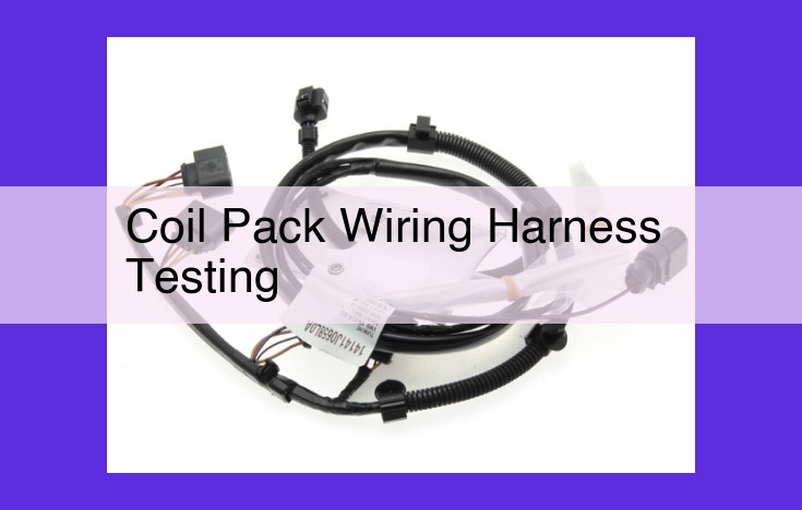
The coil pack wiring harness serves as the electrical lifeline connecting the ignition coils to the vehicle’s battery and ignition module. Its primary function is to transmit high-voltage impulses from the ignition module to the coils, which in turn generate the intense spark required to ignite the fuel-air mixture in the engine’s cylinders.
The harness is constructed of durable materials capable of withstanding the extreme heat and vibration of the engine compartment. It consists of multiple wires, each with a specific color-coded insulation to facilitate proper connection and identification. These wires are meticulously arranged and protected within a conduit or sheath to prevent damage and ensure electrical isolation.
Unmasking Electrical Faults: Open/Short Circuit Testing
Open circuits occur when a break in the wire disrupts the electrical path, preventing current flow. Short circuits, on the other hand, arise when two wires make contact unintentionally, creating an alternative pathway for current, bypassing intended components.
Detecting open and short circuits requires Ohm’s Law, which relates voltage (V) to current (I) and resistance (R): V = IR. Using a multimeter, technicians can measure the resistance across each wire. An infinite resistance reading indicates an open circuit, while a near-zero resistance reading suggests a short circuit.
Ensuring Circuit Connectivity: Continuity Testing
Continuity testing verifies the presence of a complete electrical path without breaks or interruptions. A multimeter probe is used to check for continuity between different points in the harness. If a conductive path exists, the multimeter will emit a tone or display a low resistance reading, indicating continuity.
Preserving Electrical Isolation: Insulation Resistance Testing
The insulation surrounding each wire is crucial for preventing electrical leakage and maintaining the integrity of the circuit. Insulation resistance testing employs a megohmmeter, which applies a high voltage to the insulation and measures the resulting current flow. A low insulation resistance value indicates leakage, compromising the harness’s safety and efficacy.
Open/Short Circuit Testing: Identifying Electrical Faults
In the realm of automotive diagnostics, identifying electrical faults is crucial for ensuring optimal engine performance. Coil pack wiring harnesses play a critical role in the ignition system, distributing current to the spark plugs. A faulty wiring harness can disrupt this process, leading to a myriad of issues, from engine misfires to complete breakdowns.
To diagnose these faults, open circuit testing and short circuit testing are essential techniques. Understanding the principles of electrical circuits is key for these tests. Ohm’s Law, a cornerstone of electricity, states that the current (I) flowing through a conductor is directly proportional to the voltage (V) applied and inversely proportional to the resistance (R):
I = V / R
When a circuit is open, no current flows because the path for electron movement is broken. This can be caused by a severed wire or a faulty connection. Using a multimeter, set to the “ohms” setting, you can measure the resistance between two points in the circuit. An open circuit will exhibit an infinite resistance reading.
Conversely, a short circuit occurs when two points in a circuit are connected unintentionally, creating a low-resistance path for current to flow. This can result from worn insulation or damaged wires. A multimeter set to the “ohms” setting will indicate near-zero resistance in a short circuit.
By systematically checking the resistance between various points in the wiring harness, you can effectively identify open and short circuits. This process helps you pinpoint the precise location of the fault, facilitating quick and accurate repairs.
Continuity Testing: Ensuring Flawless Circuit Connectivity
In the intricate tapestry of automotive electronics, a vital component that ensures the smooth flow of electrical impulses is the coil pack wiring harness. This intricate network connects the coil packs to the ignition module, playing a crucial role in delivering the spark that ignites the fuel in your engine. Maintaining proper continuity within this harness is paramount for optimal engine performance and reliability.
Importance of Circuit Continuity
Continuity, the ability of an electrical circuit to conduct electricity without interruption, is essential for the proper functioning of the coil pack wiring harness. Without continuous flow of electrical signals, the coil packs cannot receive the necessary power to generate high-voltage sparks, resulting in misfiring, poor engine performance, and reduced fuel efficiency.
Using a Multimeter for Continuity Testing
To verify circuit continuity, you can employ a multimeter, a handy tool that measures electrical properties. Set the multimeter to the “continuity” or “diode” mode, which allows it to send a small current through the circuit. Connect the multimeter probes to the terminals of the wiring harness under test.
When the circuit is complete, the multimeter will typically:
- Emit a beep or display a low resistance reading (typically below 10 ohms)
- Turn on a light on the display
If the multimeter does not respond, it indicates an open circuit, a break in the wiring harness that prevents the flow of electricity. This can be caused by damaged wires, loose connections, or faulty components.
Identifying Potential Breaks
To pinpoint the exact location of a break in the wiring harness, use the multimeter probes to probe along the harness while observing the multimeter’s response. When you reach a point where the multimeter stops responding, you have likely identified the break.
Regular continuity testing of the coil pack wiring harness is a preventive measure that can help you avoid unexpected breakdowns and ensure your engine runs at its peak efficiency. By verifying the integrity of the electrical connections, you can maintain optimal ignition performance and enjoy a smooth and responsive driving experience.
Insulation Resistance Testing: Ensuring Electrical Isolation
Purpose of Insulation Resistance Testing
Maintaining electrical isolation is critical for the safe and reliable operation of coil pack wiring harnesses. Insulation resistance testing ensures that the insulation surrounding the conductors is intact and provides adequate protection against electrical leakage. By using an insulation tester, also known as a megohmmeter, we can measure the resistance between conductors and ground, effectively evaluating the integrity of the insulation.
Significance of Insulation Resistance
High insulation resistance is crucial for preventing current from flowing between conductors. This is especially important in harsh environments where moisture or contaminants can compromise the insulation’s integrity. Low insulation resistance can lead to leakage current, which can cause premature aging of the wiring harness, electrical shorts, and even electrical fires.
Detecting Leakage Current
An insulation tester applies a high voltage to the circuit and measures the current flowing through the insulation. If the insulation is compromised, a measurable current will flow, indicating leakage. By comparing the measured resistance to industry standards, we can determine if the insulation is adequate or needs repair.
By performing regular insulation resistance testing, we can proactively identify and address potential insulation failures, ensuring the safety and reliability of coil pack wiring harnesses in critical applications.
Hi-Pot Testing: Assessing Insulation Strength
Understanding Dielectric Strength and Insulation Integrity
In the world of electrical systems, insulation plays a vital role in preventing current leakage and ensuring the safe operation of components. The strength of insulation is measured by its dielectric strength, which refers to the voltage it can withstand before allowing current to flow through it.
Importance of Insulation Integrity for Coil Pack Wiring Harnesses
In the specific context of coil pack wiring harnesses, robust insulation is paramount. These harnesses are responsible for carrying high-voltage impulses to the ignition coils, which then ignite the fuel-air mixture in the engine cylinders. Faulty insulation can lead to current leakage, resulting in misfires, poor engine performance, or even catastrophic electrical failures.
High-Voltage Testing for Insulation Evaluation
To assess the insulation strength of wiring harnesses, a process known as Hi-Pot Testing is employed. This involves applying a high voltage (typically several thousand volts) to the harness to determine its dielectric breakdown point.
Conducting Hi-Pot Testing
During a Hi-Pot test, a high-voltage source is connected to the harness, and the voltage is gradually increased until the harness breaks down. The breakdown voltage indicates the point at which the insulation fails and current flows.
Interpreting Test Results
The results of Hi-Pot testing provide valuable insights into the insulation integrity of the harness. If the breakdown voltage falls below the specified minimum, it suggests that the insulation is compromised and the harness requires repair or replacement. On the other hand, passing the test with a high breakdown voltage ensures that the harness can withstand the electrical stresses it will encounter in real-world conditions.
Hi-Pot testing is a crucial step in the quality control process for coil pack wiring harnesses. By assessing their dielectric strength, it helps ensure that these harnesses meet the highest standards of safety and reliability. This, in turn, contributes to the smooth and efficient operation of the entire ignition system and, ultimately, the overall performance of the vehicle.
Functional Testing: Validating Actual Performance
To ensure that the coil pack wiring harness functions flawlessly under real-world conditions, functional testing is crucial. This involves simulating actual operating scenarios to evaluate its performance and identify potential issues.
A well-defined test plan serves as the backbone of functional testing, outlining the specific tests to be conducted, the equipment required, and the expected outcomes. Test cases provide detailed instructions, ensuring consistency and reproducibility.
Specialized test equipment plays a vital role in simulating the engine’s behavior. These devices generate electrical signals, control ignition timing, and monitor engine parameters. By mimicking real-world conditions, functional testing can uncover potential problems that may not be apparent during static testing.
During functional testing, data is meticulously documented. This includes recording test input parameters, output measurements, and any observations made during the testing process. This documentation serves as valuable evidence of the harness’s performance and can help identify trends or patterns in case of future failures.
Environmental Testing: Ensuring Reliability in Harsh Conditions
Temperature Testing:
Extreme temperatures can wreak havoc on wiring harnesses. Heat can cause insulation to melt or degrade, while cold can make it brittle and prone to cracking. Environmental chambers simulate temperature variations to assess the harness’s ability to withstand extreme heat and cold without compromising its performance.
Humidity Testing:
Moisture and humidity can lead to corrosion and electrical short circuits. Humidity chambers expose the harness to high humidity levels to evaluate its resistance to moisture penetration and corrosion. This testing ensures that the harness can function reliably in humid environments.
Vibration and Shock Testing:
Vibration and shock are common occurrences in automotive applications. Vibration tables simulate these conditions to assess the harness’s ability to withstand vibrations and shocks without causing damage. These tests are crucial for ensuring the harness’s durability in rough driving conditions.
Corrosion Testing:
Corrosion is a major threat to wiring harnesses due to exposure to moisture, salt, and chemicals. Salt spray chambers simulate these harsh environments to evaluate the harness’s resistance to corrosion. Corrosion testing helps identify any potential weaknesses in the insulation or metal connectors that could lead to electrical failures.
Environmental testing plays a critical role in ensuring the reliability of coil pack wiring harnesses under real-world conditions. By subjecting the harness to extreme temperature variations, humidity, vibration, shock, and corrosion, manufacturers and engineers can identify any potential vulnerabilities and design harnesses that can withstand these harsh environments. This testing helps prevent electrical failures, improves vehicle performance, and enhances safety for drivers.