Mastering SAE J1850 PWM empowers automotive professionals with a deep understanding of the standard’s architecture, message structure, physical and data link layer protocols, network management, fault detection, and testing techniques. This comprehensive guide encompasses PWM basics, SAE J1850 PWM’s significance, hardware specifications, error handling mechanisms, and diagnostic strategies, ensuring proficiency in designing, implementing, and troubleshooting automotive communication systems.
- Explain the concept of pulse-width modulation (PWM) and its components (duty cycle and frequency).
Imagine the world of electronics as a vast symphony, where signals dance and oscillate, carrying messages between intricate components. Among this orchestra of signals, pulse-width modulation (PWM) stands out as a versatile conductor, orchestrating power flow and communication with precision and efficiency.
PWM operates on a deceptively simple principle: by varying the width of a series of electrical pulses, it modulates the duty cycle, which is the percentage of time the pulse is turned on in a given period. Alongside the duty cycle, PWM also controls the frequency, which determines how often the pulses occur.
Like a skilled musician adjusting the volume of a note by varying the pressure on the keys, PWM allows engineers to control the amount of power delivered to a load by modulating the duty cycle. Imagine a light bulb: by increasing the duty cycle of the PWM signal, we can make the bulb shine brighter. Conversely, decreasing the duty cycle dims the light.
PWM’s versatility extends beyond power control. It also plays a critical role in communication systems, where it enables the transmission of digital data. By varying the duty cycle of pulses, we can encode binary information (1s and 0s) and transmit it across wires or wirelessly.
SAE J1850 PWM Automotive Standard:
- Discuss the overview, significance, and applications of the SAE J1850 PWM standard in automotive communication systems.
Driving Deep into SAE J1850 PWM: A Gateway to Automotive Communication
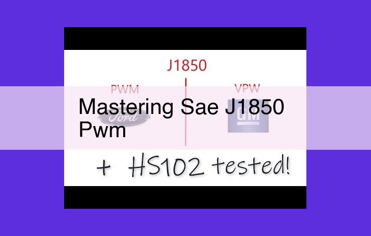
SAE J1850 PWM: The Language of Automotive Networks
In the realm of automotive engineering, seamless communication between intricate systems is paramount. Among the protocols that bridge the gap between components, SAE J1850 PWM stands out as a cornerstone of vehicle connectivity. This standard, a brainchild of the Society of Automotive Engineers (SAE), has revolutionized the way vehicles communicate, paving the way for a host of advancements in safety, comfort, and efficiency.
Significance and Applications: A Digital Lifeline
SAE J1850 PWM is a digital communication protocol that has found widespread acceptance in automotive applications. Its significance lies in its ability to transmit critical data between various modules within a vehicle, enabling them to exchange vital information and coordinate their operations. It serves as a digital lifeline, facilitating a constant flow of data that powers everything from engine control to airbag deployment.
Message Structure: Precision in Communication
At the heart of SAE J1850 PWM lies a meticulously defined message structure. Each message consists of three primary fields:
- Header: A prelude to the message, identifying its source and purpose.
- Data: The core payload, carrying the actual information being transmitted.
- Checksum: A digital fingerprint, ensuring the integrity of the message and preventing errors.
Physical Layer: The Foundation of Communication
The physical layer of SAE J1850 PWM defines the hardware aspects of communication, including wiring specifications, connector types, and signal characteristics. This layer ensures the reliable transmission of data over the physical medium, ensuring that messages reach their intended destination without corruption.
Data Link Layer: Ensuring Data Integrity
Building upon the physical layer, the data link layer focuses on framing messages, detecting errors, and managing data flow. It employs techniques such as frame synchronization and checksum verification to maintain the integrity of the data being transmitted, minimizing the risk of errors that could disrupt vehicle operation.
Message Structure: Unraveling SAE J1850 PWM’s Communication Blueprint
The SAE J1850 PWM protocol defines the precise structure of messages exchanged over its network. Like a well-crafted letter, each message is meticulously organized into distinct fields, each serving a specific purpose in conveying information. Let’s delve into the anatomy of an SAE J1850 PWM message:
Header Field: Setting the Stage
The header field, akin to the envelope of a letter, is responsible for introducing the message and providing crucial context. It comprises three primary elements:
- Start Bit: The start bit, like a bell’s chime, signals the beginning of a new message, alerting the receiver to brace for incoming data.
- Address Field: This field, analogous to an address label, identifies the intended recipient of the message. Each node on the network possesses a unique address, ensuring messages reach the correct destination.
- Control Field: Think of this field as the sender’s instructions for handling the message. It specifies the message type (such as data or request) and the number of data bytes that follow.
Data Field: The Core of the Message
The data field carries the heart of the message – the actual information being communicated. Here, data is conveyed in bytes, with each byte representing a specific piece of information, such as sensor readings or command parameters. The length of the data field varies depending on the message type and the amount of data it needs to convey.
Checksum Field: Ensuring Message Integrity
The checksum field, akin to a quality control inspector, plays a crucial role in ensuring the integrity of the message. It contains a calculated value that serves as a fingerprint of the message. Upon receiving the message, the receiver recalculates the checksum and compares it to the received value. If they match, the receiver can be confident that the message has not been corrupted during transmission.
By adhering to this well-defined message structure, SAE J1850 PWM ensures that messages are transmitted accurately and interpreted correctly, fostering seamless communication within the automotive network.
Physical Layer Protocol for SAE J1850 PWM:
- Describe the wiring specifications, connector types, signal levels, and timing characteristics used in SAE J1850 PWM physical layer communication.
Physical Layer Protocol for SAE J1850 PWM
The physical layer of the SAE J1850 PWM protocol establishes the foundational infrastructure for data transmission. It defines the wiring specifications, connector types, signal levels, and timing characteristics that ensure reliable communication between devices.
Wiring Specifications and Connector Types
The SAE J1850 PWM physical layer employs a twisted pair wiring configuration, where two insulated copper wires are twisted together to minimize electromagnetic interference. The standard specifies the use of 2-pin connectors, typically with a deutsch connector or mini-timer connector.
Signal Levels and Timing Characteristics
The signal levels used in SAE J1850 PWM communication are positive only, without negative voltage swings. The idle state is represented by a voltage level of approximately 5V, while the active state corresponds to a voltage level of 0V.
The timing characteristics of the SAE J1850 PWM physical layer are crucial for ensuring proper reception and interpretation of data. The standard defines a bit rate of 41.6kbit/s, with each bit represented by a PWM pulse. The duty cycle of the PWM pulse, which determines the proportion of time it remains in the active state, conveys the binary information.
In summary, the physical layer protocol for SAE J1850 PWM establishes the physical infrastructure and signal characteristics that facilitate the reliable transmission of data between automotive devices. Understanding and adhering to these specifications are essential for effective communication on SAE J1850 PWM networks.
Understanding the SAE J1850 PWM Data Link Layer Protocol
The SAE J1850 Pulse-Width Modulation (PWM) standard defines the communication protocol used in automotive applications. The data link layer of this protocol plays a crucial role in ensuring reliable and efficient data transmission.
Frame Synchronization
In the SAE J1850 PWM data link layer, frame synchronization is achieved using a start bit, which is a low-to-high voltage transition, and a stop bit, which is a high-to-low voltage transition. The start bit signals the beginning of a frame, while the stop bit indicates its end.
Error Detection
To detect errors in transmission, the SAE J1850 PWM protocol employs a checksum. Each frame includes a checksum calculated based on the data field. The receiving node recalculates the checksum and compares it with the one received. If the checksums match, it indicates that the frame was received without errors.
Additional Techniques for Reliability
Beyond frame synchronization and error detection, the SAE J1850 PWM data link layer also utilizes other techniques to enhance reliability:
- Parity bit: An additional bit added to the frame to ensure that the number of ‘1’ bits is always even or odd.
- Bit stuffing: A technique where an extra bit is inserted into the data stream to prevent the occurrence of an extended sequence of ‘0’ or ‘1’ bits, which can disrupt synchronization.
- Automatic Repeat Request (ARQ): A mechanism that allows the receiving node to request the retransmission of a frame if an error is detected.
By incorporating these techniques, the SAE J1850 PWM data link layer ensures robust and reliable communication between automotive components. Its mastery is essential for engineers and enthusiasts working with automotive electronics systems.
Network Management in SAE J1850 PWM
Amidst the intricate tapestry of automotive communication protocols, SAE J1850 PWM stands out as a cornerstone for managing data transmission within vehicle networks. This carefully orchestrated system ensures that data flows seamlessly and efficiently, facilitating uninterrupted communication among various electronic control modules (ECMs) and sensors.
At the heart of network management in SAE J1850 PWM lie three fundamental mechanisms: node addressing, arbitration, and priority.
Node Addressing: Each ECM or sensor on the network is assigned a unique ID (Identification), acting as its digital address. Through this ID, messages can be precisely routed to their intended recipients.
Arbitration: When multiple devices on the network attempt to transmit simultaneously, arbitration comes into play. Each message includes a start bit with a dominant value (low voltage). The device with the lowest ID is granted the exclusive right to transmit. This simple yet effective mechanism prevents data collisions and ensures orderly communication.
Priority: To cater to the varying importance of messages, SAE J1850 PWM incorporates a priority mechanism. This mechanism assigns each message a priority level between 0 (highest) and 7 (lowest). Messages with higher priority gain preferential access to the network, ensuring critical data is delivered with minimal delay.
The seamless interaction of these mechanisms orchestrates a symphony of communication within SAE J1850 PWM networks. Nodes effortlessly exchange data, ensuring that essential functions, such as engine control, emissions monitoring, and safety features, operate without interruption. By mastering the intricacies of network management in SAE J1850 PWM, automotive engineers and enthusiasts empower themselves to design and maintain reliable and efficient vehicle communication systems.
Fault Detection and Isolation for SAE J1850 PWM:
- Describe the methods used to generate error codes, perform diagnostics, and isolate faults in SAE J1850 PWM systems.
Fault Detection and Isolation in SAE J1850 PWM Systems
Unveiling the intricate tapestry of SAE J1850 PWM automotive communication demands a deep dive into fault detection and isolation techniques. These mechanisms are the unsung heroes that safeguard the integrity and reliability of these systems. So, let’s embark on a journey to explore how SAE J1850 PWM ensures seamless communication in the face of adversity.
Error Code Generation
At the heart of fault detection lies the ability to identify and report errors. SAE J1850 PWM employs a sophisticated error code generation system that monitors the communication stream for any deviations from the norm. When an anomaly is detected, it is promptly translated into a specific error code that provides valuable insights into the nature of the fault.
Diagnostic Routines
Armed with error codes, the system initiates a series of diagnostic routines to pinpoint the root cause of the malfunction. These routines involve carefully scrutinizing the communication bus, checking the timing characteristics, and assessing the integrity of the transmitted signals. By meticulously analyzing the error codes and the results of the diagnostic routines, engineers can swiftly identify the culprit.
Fault Isolation
Once the faulty component or subsystem has been identified, it is time for fault isolation. SAE J1850 PWM excels at this task through its ingenious design. By temporarily disabling or removing individual nodes from the network, the system can isolate the problem to a specific component. This approach allows for targeted troubleshooting and efficient repair or replacement.
Mastering fault detection and isolation in SAE J1850 PWM systems empowers engineers and enthusiasts to maintain reliable and efficient automotive communication networks. Understanding the error code generation mechanisms, diagnostic routines, and isolation techniques provides the confidence to diagnose and resolve any issues that may arise, ensuring that your vehicle’s communication systems operate at their peak performance.
Testing and Validation for SAE J1850 PWM
To ensure reliable and efficient communication on SAE J1850 PWM networks, rigorous testing and validation are crucial. These procedures help identify and correct potential issues, ensuring the integrity and performance of the system.
Simulation and Emulation
One technique involves simulation, where a virtual environment replicates the behavior of the SAE J1850 PWM system. This approach allows engineers to test and troubleshoot the system without the need for physical hardware. Software tools can simulate various operating conditions, message traffic, and fault scenarios, providing insights into system performance and response.
Emulation, on the other hand, involves using specialized hardware to mimic the behavior of real-world components. This approach provides a more realistic testing environment, allowing engineers to test the interaction between different modules and components. Emulation systems can simulate signal levels, timing, and other communication parameters with greater accuracy.
Hardware Testing
Hardware testing involves connecting the actual SAE J1850 PWM system to specialized test equipment. Oscilloscopes and logic analyzers are commonly used to monitor and analyze signals, verifying timing characteristics and message structure. Data loggers can be employed to capture and record message traffic, enabling comprehensive analysis.
Fault injection techniques can be used to intentionally introduce errors into the system, testing its ability to detect and respond to various fault conditions. This helps identify potential weaknesses and vulnerabilities in the system design.
Thorough testing and validation procedures are essential for ensuring the robustness and reliability of SAE J1850 PWM systems. By employing a combination of simulation, emulation, and hardware testing, engineers can identify and resolve potential issues, ensuring the system meets the demanding requirements of automotive communication.