Varistor testing involves a step-by-step process to assess their functionality in electrical circuits. Safety precautions, such as using proper PPE, should be strictly followed. Varistors can be identified by their markings and voltage ratings. In-circuit testing involves measuring resistance using a multimeter. Out-of-circuit testing uses a variable voltage power supply to determine breakdown voltage. Test results are compared to specifications to evaluate varistor performance. Troubleshooting may be necessary to identify failures and circuit issues. Proper documentation and reporting ensure accurate record-keeping and communication of findings.
- Explain the significance of varistors in electrical circuits.
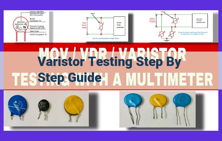
- Provide a brief overview of varistor testing procedures.
Harnessing the Power of Varistors: Varistors play a crucial role in safeguarding electrical circuits from the wrath of harmful voltage surges. They act as valiant protectors, dissipating excess voltage like tiny shock absorbers.
Testing Varistors: A Safe and Essential Practice: Verifying the integrity of varistors is paramount. This blog will delve into the proper procedures for testing these indispensable circuit guardians, ensuring reliable performance and optimal circuit protection.
Safety First: Essential Precautions for Varistor Testing
Varistors, those unsung heroes of electrical circuits, play a crucial role in safeguarding electronic devices from damaging voltage surges. However, testing these protective components requires utmost caution, as they can pose significant electrical hazards.
Electrical Hazards to Consider
Varistors, when subjected to high voltage, can release stored energy, leading to electrical shocks or even explosions. It’s paramount to be fully aware of these risks before embarking on any testing procedures.
Importance of Personal Protective Equipment (PPE)
Donning appropriate PPE is non-negotiable during varistor testing. Insulated gloves, safety glasses, and flame-resistant clothing are your shields against potential electrical hazards. Ensure that your PPE meets industry standards and fits comfortably.
Electrical Safety Guidelines
- Always disconnect power before handling any electrical component, including varistors.
- Use insulated tools to prevent accidental contact with energized circuits.
- Test in a well-ventilated area to dissipate any toxic fumes that may arise.
- Keep a safe distance from the varistor during testing, especially when using high voltage.
- Never touch the varistor leads with bare hands.
Identifying Varistors: A Guide to Unraveling Circuit Board Mysteries
In the realm of electronics, varistors serve as unsung heroes, protecting circuits from the wrath of voltage surges. To effectively test these crucial components, it’s imperative to first master the art of identifying them. Let’s embark on this detective mission and learn how to decipher varistor markings, understand voltage ratings, and locate these elusive devices on circuit boards.
Unveiling Varistor Markings
Varistors often bear cryptic markings that hold valuable information. These markings typically include a voltage rating and a manufacturer’s code. For instance, a varistor marked “130V 271″ indicates a 130-volt rating and is manufactured by 271.
Understanding Voltage Ratings and Maximum Surge Current
The voltage rating of a varistor specifies the maximum voltage it can withstand without significant leakage current. It’s crucial to ensure that the varistor’s voltage rating exceeds the highest voltage present in the circuit. Additionally, varistors have a specified maximum surge current rating, representing the peak current they can handle without failing.
Locating Varistors on Circuit Boards or Schematics
Varistors can be found on circuit boards as discrete components with two terminals or as part of network configurations. To locate them on schematics, look for symbols that resemble two parallel lines connected by a zigzag line. These symbols represent the two terminals of the varistor and the surge suppression mechanism.
By mastering the art of identifying varistors, you’ll become a circuit board detective, empowered to uncover these hidden protectors and ensure the longevity of your electronic devices.
In-Circuit Varistor Testing: A Guide for Electrical Troubleshooting
Varistors, vital components in electrical circuits, safeguard sensitive electronic devices from damaging voltage surges. Ensuring their proper function is crucial, and in-circuit testing offers a quick and efficient method for evaluating varistors without removing them from the circuit board.
To begin, select the appropriate multimeter with a resistance measurement function. Set it to the ohms (Ω) range and connect the test leads to the varistor’s terminals. Read the resistance value and compare it to the expected range for the specific varistor type. Different varistors exhibit distinct resistance characteristics, so consult the datasheet for the expected resistance value.
Typical resistance ranges for various varistor types:
- Zinc oxide varistors (MOVs): 0.5-100 MΩ
- Silicon carbide varistors (SiC): 1-100 MΩ
- Polymer thick film varistors (PTFV): 0.1-100 MΩ
If the resistance measurement falls outside the expected range, it indicates a potential issue with the varistor. A significant deviation from the specified resistance range could suggest damage or degradation. Further testing is recommended to confirm the varistor’s functionality.
Out-of-Circuit Varistor Testing
When it comes to out-of-circuit varistor testing, it’s crucial to understand the setup for breakdown voltage testing. Before you dive into the process, you’ll need a trusty variable voltage power supply. This trusty tool will help you ramp up the voltage until you reach the varistor’s breakdown voltage, just like a brave explorer seeking the summit of a mountain.
To set up the testing rig, connect the varistor between the power supply’s output terminals. Then, cautiously increase the voltage while monitoring the current flow through the device. As the voltage climbs, the current will remain relatively low until the varistor’s breakdown voltage is reached. At this point, the varistor will undergo a dramatic change, with the current surging as it switches from its high-resistance state to a low-resistance state.
Measuring the breakdown voltage is the key to understanding the varistor’s performance. Use a multimeter to measure the voltage across the varistor while gradually increasing the power supply voltage. Record the voltage at which the current surges, as this is the varistor’s breakdown voltage.
Finally, compare the measured breakdown voltage to the varistor’s specifications. A significant deviation could indicate a problem with the varistor or a potential issue within the circuit. By performing out-of-circuit varistor testing, you can ensure the device is operating within its specified parameters, protecting your circuits from harmful voltage spikes.
Evaluating Test Results
When assessing the health of a varistor, it’s crucial to compare your test results against the specifications provided in the datasheet. This comparison will reveal whether the varistor is performing within acceptable limits or if further investigation is required.
One key parameter to examine is the resistance. For in-circuit testing, the resistance should fall within a specific range for a given varistor type. If the resistance is significantly higher or lower than expected, it may indicate a problem with the varistor or the circuit it’s in.
For out-of-circuit testing, the breakdown voltage is a critical specification. It represents the voltage level at which the varistor begins to conduct electricity. Your test results should closely match the datasheet specifications for breakdown voltage. Any significant deviations could indicate a defective varistor or other issues in the circuit.
By carefully scrutinizing your test results against the datasheet specifications, you can gain valuable insights into the condition of the varistor. Any discrepancies should be noted and investigated further to ensure the safety and reliability of your electrical circuits.
Troubleshooting Varistor Failures: Unraveling the Mysteries
Varistors, those unsung heroes of electrical circuits, play a vital role in protecting sensitive electronic components from harmful voltage spikes. But even these resilient devices can succumb to the relentless forces of electricity, leaving behind a trail of troubleshooting headaches.
Common Varistor Failure Modes and Their Culprits
- Electrical Overstress: Excessive voltage or current can literally blow a varistor to smithereens.
- Thermal Overstress: Heat can be a varistor’s nemesis, causing it to overheat and fail.
- Mechanical Stress: Physical damage, such as bending or vibration, can weaken a varistor’s structure.
- Aging: Like all electronic components, varistors have a finite lifespan and eventually wear out.
- Environmental Factors: Moisture, dust, and extreme temperatures can also contribute to varistor failures.
Deciphering the Clues: Analyzing Test Results
When a varistor fails, it leaves behind telltale signs that can help you pinpoint the underlying cause.
- In-Circuit Testing: By measuring the resistance of a varistor while it’s still connected to the circuit, you can identify open or short circuits.
- Out-of-Circuit Testing: For a more comprehensive evaluation, remove the varistor and use a variable voltage power supply to test its breakdown voltage. Compare the measured value to the specified breakdown voltage in the varistor’s datasheet.
Potential Circuit Issues Revealed
The results of your varistor testing can shed light on potential issues within the circuit.
- Voltage Surges: High measured breakdown voltage may indicate excessive voltage spikes in the circuit.
- Overheating: A significantly reduced breakdown voltage suggests thermal overstress, possibly due to poor heat dissipation.
- Component Failures: Varistor failures can sometimes point to problems with other components in the circuit.
By carefully analyzing test results and considering the possible failure modes, you can unravel the mysteries surrounding varistor failures and restore your circuits to optimal operation.
Documenting and Reporting Varistor Testing
Thorough documentation and reporting of varistor testing results are crucial for effective troubleshooting and future reference. To ensure comprehensive documentation, follow these guidelines:
-
Record Test Results: Meticulously note all test results, including measured resistance and breakdown voltage values. Include the date of testing, the equipment used, and any relevant observations.
-
Include Observations and Troubleshooting Notes: Capture any unusual behavior or patterns observed during testing. Document any troubleshooting steps taken to identify potential circuit issues.
-
Report Findings to Stakeholders: Communicate the test results and any identified issues to relevant stakeholders, such as engineers, maintenance personnel, or quality control teams. Include clear and concise explanations of the findings to aid in decision-making.
By adhering to these documentation and reporting practices, you can establish a reliable record of varistor testing results, facilitate future troubleshooting efforts, and ensure that critical information is accessible to those who need it.