SWR (Standing Wave Ratio) is crucial in ham radio for matching impedance between antenna and transmission line. High SWR indicates impedance mismatch, leading to signal loss and equipment damage. Measurement techniques and interpretation of SWR values are essential. Understanding impedance basics helps optimize antenna and feedline selection. Baluns and tuners play vital roles in impedance matching. Strategies for achieving low SWR include proper antenna placement, feedline matching, and tuner adjustments. SWR management is key for optimal ham radio performance, ensuring efficient signal transmission and reception.
- Importance of impedance matching in ham radio systems
- Role of SWR as an indicator of impedance mismatch
Understanding the Importance of Impedance Matching in Ham Radio Systems
In the captivating world of ham radio, seamless communication is paramount. Impedance matching, a crucial concept in electrical engineering, plays a pivotal role in achieving this optimal performance. Imagine your ham radio system as a symphony orchestra, where each instrument (component) must play harmoniously to produce a clear and coherent sound. Impedance matching ensures that each component is in tune with the others, maximizing signal transmission and preventing interference.
The Role of SWR: A Diagnostic Tool for Impedance Mismatch
A key indicator of impedance mismatch is Standing Wave Ratio (SWR). SWR measures the ratio of maximum voltage to minimum voltage along a transmission line, and it provides valuable insights into the impedance relationship between your antenna and transmitter. A high SWR indicates a significant mismatch, while a low SWR suggests a more ideal condition. Understanding SWR values is essential for diagnosing and resolving impedance issues, ensuring that your ham radio system operates at its peak.
Measuring and Understanding SWR: A Critical Step for Ham Radio Success
In the world of ham radio, Standing Wave Ratio (SWR) plays a crucial role in ensuring optimal performance. SWR quantifies the impedance mismatch between an antenna and its transmission line, indicating the amount of power reflected back towards the transmitter. By understanding how to measure and interpret SWR values, you can optimize your ham radio system for maximum efficiency.
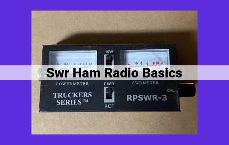
Measuring SWR with an SWR Meter
Measuring SWR requires an SWR meter, a device that connects between your transmitter and antenna. The SWR meter reads the forward and reflected power levels, calculating the SWR using the formula SWR = (Forward power + Reflected power) / (Forward power – Reflected power).
Proper **SWR measurement requires the following steps:**
- Connect the **SWR meter in series with your antenna.**
- Key up your transmitter in SSB or CW mode.
- Read the **SWR value on the meter’s display.**
Interpreting SWR Values and Their Implications
The SWR value provides valuable information about the impedance mismatch between the antenna and transmission line. A low **SWR (ideally close to 1:1) indicates a good impedance match, allowing for maximum power transfer.** Conversely, a high **SWR (above 2:1) indicates a significant mismatch, resulting in power loss and potential damage to your transmitter.**
General implications of **SWR values:**
- SWR below 1.5:1: Good impedance match, minimal power loss.
- SWR between 1.5:1 and 2:1: Acceptable match, but some power loss may occur.
- SWR above 2:1: Significant impedance mismatch, substantial power loss, and potential transmitter damage.
By understanding the implications of SWR values, you can take steps to ensure your ham radio system operates at peak efficiency.
Impedance Basics: Understanding the Role of Impedance in Ham Radio Systems
In the world of ham radio, impedance plays a crucial role in ensuring optimal signal transmission and reception. Impedance is a measure of the opposition to the flow of alternating current (AC) and is affected by the circuit’s resistance, inductance, and capacitance.
For effective communication, it’s essential to match the impedance between your antenna and transmission line. When impedance is mismatched, it can lead to signal reflections, power loss, and compromised system performance. Just like a poorly fitted key doesn’t turn a lock smoothly, mismatched impedance hinders the efficient transfer of energy.
Think of impedance as a bridge between your antenna and transmission line. When the bridge is well-built, with properly sized components, the signal flows effortlessly. However, if the bridge is too narrow or too wide, some of the energy is lost, preventing the signal from traveling smoothly.
Antenna Considerations: The Keystone of Impedance Matching
When it comes to selecting an antenna for your ham radio system, understanding its design and impedance characteristics is paramount. A plethora of antenna types grace the realm of ham radio, each with its own unique impedance profile.
Common Antenna Types and Their Impedance
- Dipole Antennas: The quintessential ham radio antenna, dipoles exhibit a resonant impedance of approximately 75 ohms.
- Vertical Antennas: These antennas, often used for ground-wave communication, typically have an impedance of 50 ohms or 75 ohms.
- Yagi Antennas: These directional antennas, popular for distance communication, have an impedance that varies depending on their design, typically ranging from 25 ohms to 100 ohms.
Antenna Design and Impedance
The physical design of an antenna significantly influences its impedance. Factors such as the length, shape, and materials used in its construction all play a role. For instance, a longer dipole antenna will have a lower impedance than a shorter one. Similarly, an antenna made of a thin wire will have a higher impedance than one made of a thicker conductor.
Matching Antenna Impedance to Your System
Choosing an antenna with an impedance that closely matches the impedance of your transmission line is crucial. A mismatch between the two can result in standing waves and power loss. To avoid these issues, it’s recommended to match the impedance of the antenna to the characteristic impedance of the transmission line, typically 50 ohms.
By carefully considering the antenna design and matching its impedance to your system, you can ensure optimal signal transmission and reception, maximizing the performance of your ham radio setup.
Feedline Characteristics and Their Impact on SWR
In the world of ham radio, the connection between your antenna and transmitter plays a crucial role in the efficient transfer of radio waves. This connection is made possible by the feedline, a vital component that significantly impacts your system’s performance. Understanding the characteristics of feedlines and how they affect SWR (Standing Wave Ratio) is essential for optimizing your ham radio setup.
Feedlines come in various types, each with its own unique set of properties. The most common types used in ham radio are coaxial cable, twin-lead, and ladder line. Coaxial cable, characterized by a central conductor within a cylindrical shield, is popular for its low loss and weather resistance. Twin-lead, constructed of two parallel conductors separated by insulation, is a cost-effective option often used for short runs. Ladder line, featuring two parallel conductors spaced apart by insulators, is highly efficient but requires careful installation.
The type of feedline you choose should align with the frequency range and power level of your system. For example, coaxial cable is suitable for high-frequency applications, while ladder line excels at handling higher power levels. It is crucial to consult the specifications of your equipment to determine the appropriate feedline type.
In addition to type, the length and impedance of the feedline also influence SWR. The length of the feedline, measured in multiples of half-wavelengths, can create standing waves on the line, resulting in SWR variations. Impedance, a measure of the resistance to current flow, must match between the antenna and the transmission line to minimize SWR.
Proper impedance matching is essential for efficient power transfer. Mismatched impedance can cause reflections on the feedline, leading to increased SWR and power loss. To achieve optimal performance, it is recommended to use a feedline with the same characteristic impedance as your antenna. Common impedance values for feedlines include 50 ohms and 75 ohms.
By carefully selecting and installing the appropriate feedline, you can minimize SWR and optimize the performance of your ham radio system. Understanding the characteristics of feedlines and their impact on SWR empowers you to make informed decisions that enhance your operating experience.
Understanding Baluns: Essential Tools for Impedance Matching in Ham Radio Systems
In the captivating world of ham radio, impedance matching is paramount for achieving optimal performance. Baluns, unassuming yet indispensable devices, play a pivotal role in ensuring seamless signal transmission by bridging the impedance gap between antennas and transmission lines.
What is a Balun?
Simply put, a balun is an electrical device designed to transform the impedance of a circuit. In ham radio applications, baluns are primarily used to match the impedance of unbalanced antennas (such as dipoles and verticals) to the balanced impedance of transmission lines (coaxial cables).
Types of Baluns and Their Applications
The ham radio aficionado’s toolbox boasts a variety of balun types, each tailored to specific applications:
- Current baluns: By inducing a current in an auxiliary conductor, current baluns convert an unbalanced signal to a balanced one. They are commonly used with dipole antennas and ground-mounted vertical antennas.
- Voltage baluns: These baluns utilize a transformer to match impedance levels. They are particularly effective with balanced antennas that require a higher voltage standing wave ratio (VSWR).
- Unun baluns: Ununs (a contraction of “one to one”) are transformers that maintain the same impedance on both sides. They primarily serve as matching devices for unbalanced antennas connected to balanced feedlines.
The Benefits of Baluns
The incorporation of baluns into your ham radio system yields a plethora of benefits:
- Reduced SWR: Baluns effectively reduce SWR, minimizing signal loss and preventing damage to your equipment.
- Enhanced Signal Quality: By matching impedance, baluns ensure that signals travel with minimal distortion, resulting in improved signal clarity and range.
- Antenna Protection: Some baluns provide an additional layer of protection by isolating the antenna from ground currents, reducing the risk of damage during lightning strikes.
Choosing the Right Balun
Selecting the appropriate balun for your system requires careful consideration:
- Antenna Type: Determine the type of antenna you are using, as different baluns are designed for specific antenna configurations.
- Frequency Range: Ensure that the balun covers the frequency range you will be transmitting and receiving.
- Power Handling Capability: Choose a balun that can withstand the power levels you will be using to avoid overheating or damage.
By integrating baluns into your ham radio system, you embark on a journey towards optimal performance, ensuring clear, reliable communication and a fulfilling radio experience.
Matching Impedance with Tuners: The Key to Optimal Performance
In the realm of ham radio, impedance matching is critical for ensuring seamless communication and maximizing system efficiency. Tuners play a vital role in this process, enabling you to adjust the impedance of your antenna and transmission line to achieve a perfect match.
Function of a Tuner
A tuner is an essential device that allows you to fine-tune the impedance of your antenna system. By introducing adjustable components, such as inductors and capacitors, tuners create a path for electrical signals to flow efficiently between your antenna and transmitter or receiver. This impedance matching ensures that maximum power is transferred from your transmitter to the antenna, resulting in better signal strength and range.
Types of Tuners
Various types of tuners are available, each with its unique characteristics.
- Antenna Tuners: These tuners are connected directly to the antenna and are used to match the antenna’s impedance to the transmission line. They are particularly useful for antennas with narrow bandwidths or those that may be affected by factors such as weather conditions.
- Line Tuners: These tuners are installed in the transmission line between the antenna and the transmitter or receiver. They are primarily used to compensate for impedance mismatches caused by the length or characteristics of the transmission line.
- Coupler Tuners: These tuners are designed for use with multiple antennas or when the antenna and transmission line are not easily accessible. They allow you to switch between antennas and match the impedance for each, providing a versatile solution for complex antenna systems.
Choosing the Right Tuner
Selecting the right tuner depends on your specific needs and system configuration. Consider factors such as:
- Frequency range: Ensure that the tuner supports the frequency range you operate on.
- Power handling capacity: Choose a tuner that can handle the power output of your transmitter.
- Flexibility and ease of use: Look for tuners with features that meet your operational requirements, such as automatic tuning or memory presets.
Optimizing Performance with Tuners
To optimize the performance of your ham radio system, it is crucial to properly use and adjust your tuner. Follow these tips:
- Start with a low SWR: Measure the SWR (standing wave ratio) of your antenna system before making any adjustments. Aim for an SWR of 1:1 or as close to it as possible.
- Adjust the tuner slowly: Gradually adjust the tuner’s settings until you reach the lowest SWR. Avoid over-adjusting, as this can introduce additional impedance mismatches.
- Test and re-adjust: After adjusting the tuner, test your system’s performance and re-adjust if necessary. Repeat this process until you achieve the desired SWR.
By utilizing tuners effectively, you can overcome impedance mismatches and ensure that your ham radio system operates at peak efficiency. Remember, proper impedance matching is the key to maximizing signal strength, extending range, and enjoying optimal performance in your ham radio adventures.
Optimizing Performance through SWR Management
In the realm of ham radio, achieving optimal system performance hinges on managing your Standing Wave Ratio (SWR). An elevated SWR indicates a mismatch between your antenna and transmission line, resulting in lost power and potential damage to your equipment. To ensure seamless communication and prevent costly repairs, it’s essential to implement strategies for achieving a low SWR.
Achieving a Low SWR
Several effective approaches can help you minimize SWR in your system:
- Use the Correct Antenna: Opt for an antenna designed to match the characteristic impedance of your transmission line. A mismatch in impedance between these components can significantly elevate SWR.
- Adjust Antenna Height and Position: Experiment with the height and placement of your antenna to find the optimal location for minimum SWR.
- Employ a Balun: Utilize a balun (balunced-to-unbalanced transformer) to convert unbalanced signals to balanced signals or vice versa, helping to reduce SWR in certain scenarios.
- Install a Tuner: Incorporate a tuner into your system to fine-tune the impedance matching between your antenna and transmission line, effectively lowering SWR.
Troubleshooting SWR Issues
If you encounter elevated SWR, there could be underlying issues requiring attention:
- Check for Shorts and Opens: Inspect your transmission line and antenna for any physical damage or loose connections that might be causing SWR problems.
- Examine Feedline Length: Ensure that the length of your transmission line is not an exact multiple of a half-wavelength, as this can lead to high SWR.
- Evaluate Antenna Connections: Verify that your antenna is properly connected to the transmission line and that any connectors are secure.
- Seek Professional Assistance: If you’re unable to resolve SWR issues on your own, don’t hesitate to consult with an experienced ham radio operator or technician for guidance.
By implementing these strategies and troubleshooting techniques, you can effectively manage SWR in your ham radio system. Maintaining a low SWR not only enhances signal clarity and range but also safeguards your equipment from potential damage. Embrace these best practices to enjoy a seamless and enjoyable ham radio experience.